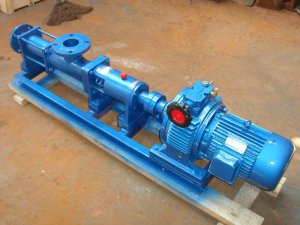
How a single screw pump works
The single screw pump is a rotor type positive displacement pump which relies on the screw and the bushing to mesh with each other to produce a volume change in the suction chamber and the discharge chamber to transport the liquid. It is an internally meshed closed screw pump, the main working part consisting of a bushing (stator) with a double-headed spiral cavity and a single-headed screw (rotor) meshing therewith in the stator cavity. When the input shaft drives the rotor to rotate around the center of the stator through the universal joint, the stator-rotor pair continuously meshes to form a sealed cavity. The sealed chambers are uniformly moved in a constant axial direction, and the conveying medium is passed from the suction end to the stator. — The rotor pair is delivered to the extrusion end, and the medium sucked into the closed chamber flows through the stator without being agitated and destroyed. Single screw pump classification: integral stainless steel single screw pump, shaft stainless steel single screw pump.
The screw has a single-start thread, and any cross section is a circle with a radius R. The center of the section is on the spiral line and is offset from the axis of the screw by an eccentricity e. The number of heads is rotated around the axis and moved in the axial direction. More than Lobes: The number of heads T1 of the stator of the screw is one more than the number of heads T2 of the rotor, that is, T1=T2+1. Their ratio becomes the head ratio. Screw pumps can be divided into single (1:2) and long (2:3, 3:4). The greater the number of heads, the greater the output torque of the screw pump and the lower the speed. Conversely, the smaller the torque output, the higher the speed. The inner surface of the bushing has a double thread, and its arbitrary section is an oblong circle. The two ends are semicircles with a radius of R (equal to the radius of the screw section), and the middle is a straight section with a length of 4e. Any section of the bushing is the same long circle, but is offset from each other by an angle.

After the screw is inserted into the bushing, a closed chamber is formed between the surface of the screw and the threaded surface of the bushing, and any section is also divided into upper and lower crescent-shaped working chambers (as shown in Figures 1-3). When the screw rotates, the volume of a working chamber near the suction chamber gradually increases to form a negative pressure, and the liquid is sucked into the working chamber by the pressure difference. As the screw continues to rotate and the working chamber volume continues to increase, the chamber closes and pushes the liquid axially toward the extrusion chamber. At the same time, the upper and lower working chambers alternately circulate and discharge the liquid, so that the liquid is continuously pushed axially from the suction chamber toward the pressing chamber.
The specification of the pump is determined according to the nature of the liquid to be transported, the flow rate and the pressure, and the speed of the pump is selected by the viscosity and corrosivity of the transported liquid as the main parameters to ensure reliable operation of the pump.
The design speed of the pump is to allow high speed when conveying clean water or clean water with similar non-corrosive liquid. In actual use, due to different media properties and life requirements, the selection should generally be lower than the design speed. For high viscosity and granular media, the design speed is generally 1/2-1/3 or lower. The low speed is beneficial to the wear of the pump, but after the use, the wear flow of the stator decreases, so the speed can be increased appropriately. To compensate for the decline in traffic is also a common policy. The temperature of the transport medium should be between -10 °C and 80 °C and in special cases up to 120 °C.
Each stage of the pump (one lead of the stator) has a normal pressure of 0.6 MPa and a maximum of 0.8 MPa for a short period of time (not more than 30 minutes). The volumetric efficiency at the same output pressure is gradually reduced when worn. When pumping clean water, the high suction stroke is 8 meters, and the actual use is recommended not to exceed 6.5 meters. When pumping high viscosity medium, it should be sucked in with positive pressure.

